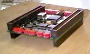
In a next step you press the stacking connector through the holes. Every pin has a sharp edge which cuts into the plating of the hole in the board. As you can see in the picture below the pins of the connector looking out of the board as flag poles.
In order to shield the pins of the connector a housing receptacle is pressed from above on the board. Again, the sharp edges of the pins cut into the plastic of the receptacle forming a very stable connection.
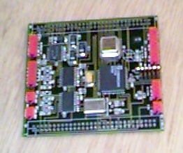
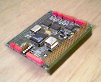
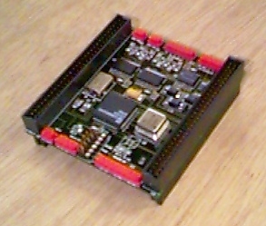
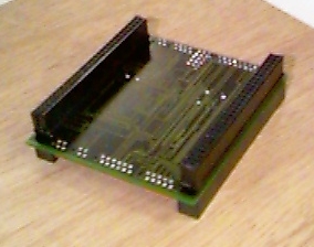
After completing the other side you get the final board. In the left picture you can see the board from above and in the right picture from below.
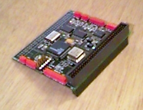
Thus, in assembling the connectors yourself, it is up to the respective needs in which row the system is stacked and how many boards are finally integrated.